Your choices so far:
1 District heating
| What is your resource? | What do you want to deliver? | What is the service the customer wants? |
| Biomass (digestible sludge) | District cooling | Comfortable indoor climate |
| Biomass (fermentable sludge) | 1 District heating | Electricity |
| Biomass (solid) | Electricity | Process cooling (< 0 °C) |
| Geothermal | Fuel: Gaseous | Process heat/steam (50 - 150 °C) |
| Sunshine | Fuel: Liquid | Process heat (150 - 1000 °C) |
| Water | Fuel: Solid | Process heat (> 1000 °C) |
| Wind | Local cooling (ind. house) | Transport |
| Residual oils/fats etc | Local heating (ind. house) |
District heating is distributed by the aid of hot water or, in some cases, steam. Most common is the distribution of hot water and in that case the system looks like this:
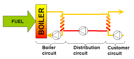
Thus, the system consists basically of three serial circuits, a boiler circuit (or more general, a heating circuit), a distribution circuit and any number of customer circuits. In practice, each customer will have two customer circuits – one for the tap water and one for the comfort heating system water. These will be manifest as two separate coils in the customer heat exchanger but for simplicity only one is included in the schematic.
Looking at the schematic above it is obvious that the district heating system contains two heat exchangers – one at the boiler end and one with the customer. From a purely theoretical point of view, it might seem wise to exclude the boiler-end heat exchanger and to use the boiler circuit water also for the distribution, but this is not recommended for two reasons:
- The part in the system most exposed to and most vulnerable to leakages is the distribution network, which may well extent for several kilometres across the township. In case of a major leakage – and if the boiler water is also the circulating water – the boiler will be dry and may suffer severe damage. Hence, the heat exchanger protects the boiler.
- For maximum efficiency in the system as a whole it is important that the return water in the distribution system is as cold as possible – preferably below 50 °C. Also the forward water should have the lowest possible temperature, and during summer this may be as low as about 65 – 70 °C. Bringing water of such low temperature into (indirect) contact with the flue gases in a heat exchanger may induce condensation of water in the flue gases with subsequent corrosion in the heat exchanger. This becomes more pronounced the higher the water content in the fuel. Hence the heat exchanger adds to the versatility and the robustness of the system.
Steam-based systems may be of interest in case there is a sufficiently large industrial demand for steam – for example at a brewery or any other food processing industry – nearby the central energy production plant.
In the case of steam distribution, there will be no heat exchanger at the boiler end but the boiler output will be directly connected to the distribution pipeline and the return to the boiler form the customer site may be steam, superheated condensate water or hot water depending on the system with the customer.
The main advantage of district heating is that the production unit becomes large and hence may accommodate
not only advanced environmental control but also advanced process control, depending on the scale. There are
no strict limits for the scales but from a qualitative point of view one may distinguish three general
categories for water-borne systems, the minimum demand being that there are at the very least two separate
buildings involved so that there is a meaning to the word "distribution":
Small systems. In the current context, a system will be considered small if the thermal load for a full year is too small to accommodate steam production. This type of systems might for example provide the heat needed for tap water and comfort heating in a university campus, for a number of public buildings in a cluster or for the buildings in a hospital area.
Intermediate systems. In the intermediate scale, the system may incorporate steam production. There can be several reasons for this: There may be a process industry or a laboratory needing steam among the customers, or the system may simply be big enough to be able to carry the extra cost associated with a steam boiler.
Large systems. A large system is one large enough to make power (i.e. electricity) production a main option. In this case, the main focus is often switched from heat to electricity efficiency but it is a mistake to look away from the heat market.
In the case of steam distribution, the above scales do not apply but you will see that steam production will be applicable only in reasonably large systems.
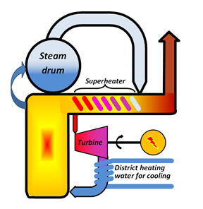
District heating production should – whenever possible – be combined with electricity production as illustrated in the schematic:
The different scales will not only affect the types of products but will also open up for different types of fuel qualities. Any fireplace is designed to work best with a specific fuel. Good combustion equipment – fed with the correct fuel at the correct rate – will provide a complete burnout of the fuel in combination with minimal amounts of air pollutants. This is one main environmental advantage with district heating: the replacement of a large number of small combustion units without proper combustion control and without flue-gas cleaning with one large unit, operated by professionals and equipped with top-rank process control and cleaning.
District cooling can also be produced in district heating plants using solid biomass as their main resource. A district heating plant of sufficient size to host also electricity production would not have biogas or ethanol or residual oils as the main fuel but it very well have integrated different energy sources such as waste combustion, solid biomass, biogas and solar energy and in such cases, these will also be the renewable resources used for district cooling production.
The whole thing may seem a bit like magic but let's work a simple example for a fictitious city:
- Assume there is a need of 10 MWh (10000 kWh) of climate cooling and this is provided through compressor cooling machines (AC-units). One may assume a cooling factor 2.5 which means that these AC units will need an input of 4000 kWh or electricity. With the European electricity mix, the total emission of greenhouse gases from electricity production amounts to approximately 6.75 kg of CO2 per kWh, so this will represent 27000 kg.
- Further assume that the same area has a total need of 10 MWh of electricity for cooking, illumination, electronics and such. This will then represent a total emission of 67500 kg CO2.
- Finally assume there is a need of 10 MWh of heat for tap- and hygiene water production and that this is produced locally in natural-gas fired heaters. Assuming the heaters to have 80% efficiency and the emission of CO2 from natural gas to be 0.275 kg of CO2/kWh one then finds a gas consumption equal to 12500 kWh and an emission 3438 kg, say 3500. The total greenhouse gas emission to supply this then becomes 98000 kg.
Now assume the very same needs but the production of three energy carriers – district cooling, electricity and district heating – takes place in a modern, biomass-fired tri-generation plant with a total efficiency 90% and an electricity efficiency 35%. Thus the efficiency for heat production becomes 55%. Finally: Biomass-firing is often assumed to have zero net emission of CO2 but this is a bit over-optimistic. For this example, 275 g/kWh biomass fuel energy is assumed. This is the same number as that used for natural gas firing in the example.
- To produce 10000 kWh (10 MWh) cooling capacity in absorption heat pumps one will have to supply first the double amount (20 MWh) of district heating water and then approximately 10% electricity (1 MWh or 1000 kWh). The district heating water is produced at 55% efficiency (90-35) so to provide 20 MWh to the heat pumps the fuel input needs be equal to 36400 kWh. But from this fuel we also get 35% electricity or a total of 12740 kWh! So when the heat for the heat pumps is produced, the side product in the form of electricity is already enough to run the heat pumps and the surplus, since the heat pumps needed 1000 kWh (1 MWh) amounts to 11740 kWh which is already more than the total amount of electricity demanded.
- Then there was a need for 10 MWh (10000 kWh) of heat and that is now produced at 55% efficiency. So the necessary fuel input becomes 18200 kWh of fuel. But at the same time, this fuel input will generate 35% electricity equal to 6350 kWh.
To sum up: 36.4 MWh of fuel energy is needed to provide the hot water to run the heat pumps and from that all the electricity needed is also obtained. Another 18.2 MWh of fuel energy is then needed to produce all the heat required. Adding up one finds a total of 54.6 MWh of fuel energy that needs be input corresponding to a CO2-emission of 15000 kg.
- Of the total fuel input 5500 kWh (10%) are lost since the total efficiency was 90%.
- 20000 kWh are used internally as hot water sent to the heat pumps to produce 10000 kWh cooling.
- 10000 kWh are delivered externally in the form of district heating.
- 1000 kWh of produced electricity are used internally to run the heat pumps.
- 18000 kWh (11740+6350) of electricity is produced and delivered to the grid.
The example illustrates how modern, biomass-fired tri-generation does not only reduce greenhouse gas emissions, from 98 tonnes to 15 in this example, but also opens up for an increase in electricity production (from 10 MWh delivered to 18 in this example) while providing at the same time climate cooling and comfort heating.
For the customer one main advantage with district heating as compared to individual heating is that the responsibility is handed over to a central, large-scale, production plant with 24-hour manning and professional personnel. Thus, the risk for breakages and the risk that the local AC-unit must suddenly be replaced at a high cost is minimised. The price paid is, of course, a fixed fee.
From an environmental point of view, the replacement of small-scale combustion units or electricity consuming AC-units operated by laymen by one central heat production plant operated by professionals will reduce the total amount of air pollutants emitted.
From a resource economy point of view, replacing electricity consumption for low-exergy energy services or the relatively low-efficiency, individual boilers by delivery of a low-exergy energy carrier and electricity production in high-efficiency plants is a step towards sustainability.
Biomass-fired tri-generation is already successfully installed in a number of Swedish cities and can be seen in full, commercial operation. Of course, the same reduction in greenhouse gas emissions would be reached if the tri-generation plant was natural-gas fired – but natural gas is not a renewable resource, so that option will not be long-term sustainable.
Once biogas injection into the European gas grid becomes big enough to make contracting of biogas for CHP and tri-generation purposes viable, that will be one main route to go. But so far the volumes injected are far too small and hence digestible biomass is, in this material and for the present time, neglected.