04-00: What is CHP?
As stated already in the introductory chapters, for example 00-01, some very fundamental things apply to all types of buildings. First, there is always a need for heat, at the very least during parts of the year, and second there is always a need for electricity. Sometimes, there is also a need for cooling during parts of the year.
It is a fundamental thermodynamical fact that fuel energy can only partly be converted into electricity using thermal power production processes, whether the process uses gas turbines, steam turbines, a combination of the two or any other thermal process. As a matter of fact, none of the processes commercially used today can convert more than approximately 55% of the fuel energy into electricity, loosing 45% of the fuel energy to cooling media.
This can be achieved if the fuel is first burned at an elevated pressure and the high-pressure gases pass a gas turbine before they enter the steam-raising device. So in a "combined cycle" plant there are both gas turbines and steam turbines. Most common, though, are condensing power plants, where water is boiled to steam and the steam is used to run turbines which in turn are connected to generators. The water may be boiled using coal, nuclear fuel, waste, biomass, gas, oil or anything else.
While top-modern, gas-fired combined-cycle power plants may have losses "only" just above 40% of the energy input, will more old-fashioned coal-power plants exhibit losses about or even exceeding 60% of the total energy input so that only about 40% of the input energy actually becomes electricity. In nuclear power plants, the losses are even bigger.
The schematic below illustrates the main parts in a condensing power plant.
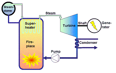
The heart of the process is the turbine where high-pressure, high-temperature steam (typically about 160 bar and 540 °C, lower in older plants and down to less than 70 bar and 300 °C in nuclear power plants) is allowed to expand to the lowest possible pressure and the lowest possible temperature. To achieve a low temperature at the turbine outlet a heat exchanger, the condenser, is placed just at the turbine steam outlet and is cooled by a cooling medium at the lowest possible temperature. In practice, "the lowest possible temperature" is the outdoor temperature at the location of the plant.
Hence, condensing power stations use ambient air with cooling towers or ambient water from the sea, from a lake or from a river as cooling media. Doing that and depending on season they may operate at condenser temperatures from about 5 °C up to about 20-25 °C and this is the reason that they can arrive at electricity conversion efficiencies as high as about 45-50% even without the additional help from gas turbines.
The main concept
In case one wants to make use of the heat losses from a condensing power station, this can only be achieved by raising the temperature of the cooling medium to such a temperature as to make it attractive for a buyer or for some kind of use.
Raising the temperature of the cooling medium is the same thing as raising the temperature in the condenser and that will reduce the electricity conversion efficiency. But this is what combined heat-and-power production CHP is about. The schematic below shows the major aspects of a CHP-system:
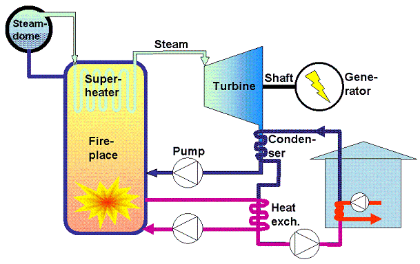
As seen from the schematic, the basic idea is to pump the cooling medium, water, for the condenser in a closed circuit and to supply the hot water thus produced to customers in a district heating (DH) network.
Assuming that the water in the district heating network is as low as 40 °C when it returns to the plant, then the condenser temperature will be just above 40 °C at the turbine outlet. As the steam from the turbine condenses, the temperature of the coolant (the DH-water) will increase, and one may assume that the temperature after the condenser is about 50 °C.
This is too low a temperature for district heating. To avoid growth of legionella bacteria, it is demanded that no customer in the district heating network the last customer being the most crucial, of course will have tap water produced at a temperature lower than about 55 °C. The exact rules for the critical temperature may differ between different states. Hence must the outgoing DH-water be significantly hotter. Therefore, the water is typically heated a bit more using a secondary heat exchanger fed with water from the boiler walls.
Once the district-heating water has achieved its correct forward temperature, it is pumped out into the district heating network where the individual customers extract heat from it through their own heat exchangers. For details, please see chapter 03-00.
The relatively high temperature in the condenser will have an adverse effect on turbine performance and the total electricity conversion efficiency will drop from about 40-45% down to about 35-40% depending on the details of the system layout.
The over-all performance of the two different types of systems is illustrated in the schematic below:
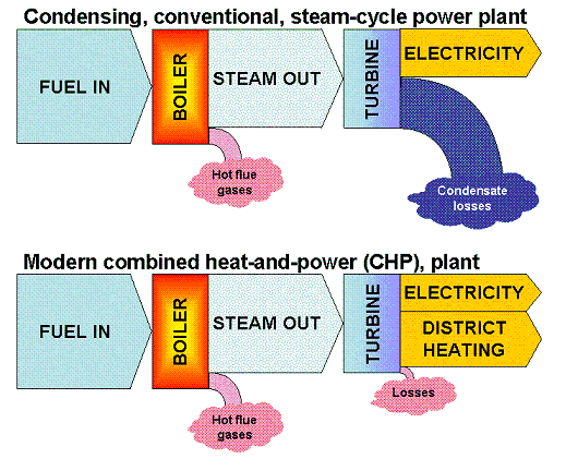
You will notice how the boiler efficiency in itself is unchanged while the portion of the energy in the steam that is actually converted into electricity is reduced in the CHP-process as compared to the condensing process. The outgoing steam quality, as measured in terms of temperature and pressure, may well be the same in both types of installations while the higher temperature at the turbine outlet in the CHP-plant accounts for the lower electricity conversion efficiency. On the other hand, the CHP process gives as a result two marketable products electricity and district heating while the condensing process gives only one, namely electricity.
Production flexibility
By a smart layout of bypass connections in the CHP-plant it is also possible to change the proportions between electricity and district heat within certain limits. The upper limit is set by the condenser temperature which is in turn determined by the return temperature from the DH-network. Therefore, it is crucial for the system performance that the district heating customers heat exchangers are correctly adjusted so as to deliver the lowest possible temperature back to the production plant.
In some cases, an extra cooling circuit has also been installed and connected to nearby rivers or lakes, so that the plant may operate in condensing mode. Such operation can sometimes be defended during shorter periods in the summertime if the price for electricity is high enough and if the marginal cost for the extra cooling circuit is low enough.
The lower limit for the ratio of electricity-to-heat is set by the steam turbine data. Once the bottom line for the steam turbine is hit, the turbine must be switched off and the plant becomes a pure heat production plant.
As an example; Consider a 110 MWTH condensing power station with the total electricity conversion efficiency 45% and with a maximum turn-down ratio of 1:3. It is also assumed that the minimum turbine load is 15 MW. Further assume 10 MW to be lost through boiler walls and flue gases. The output from this power station may then be at the very most 45 MW electricity, corresponding to 110 MW fuel power input and at the lowest 15 MW electricity, at a total fuel input of 43 MW and anything in between.
Now consider a 110 MWTH CHP-plant for comparison. Again, the boiler losses are set at 10 MW and the maximum turn-down ratio with respect to thermal input is 1:3. Further assume that the maximum attainable electricity conversion is 38% and that this ratio can be adjusted down to 25% as long as the turbine power exceeds 15 MW but below that limit the turbine can no longer work.
• At full thermal input 110 MW fuel power input, this plant may now deliver:
- 100 MW heat but no electricity.
- 75 MW heat and 25 MW electricity if the turbine is at its minimum.
- 62 MW heat and 38 MW electricity if the turbine is at its maximum.
• At half fuel input 50 MW thermal input may the plant deliver:
- 40 MW heat but no electricity.
- 25 MW heat and 15 MW electricity.
• At minimum fuel input 33 MW fuel power the plant may deliver:
- 23 MW heat but not electricity.
You will notice the flexibility in product mix inherent with the CHP-technology, and this flexibility is the advantage strived for in combination with the radical increase in total efficiency.
Finally, consider an example where there is a demand of 1 energy unit of electricity plus 1 unit of heating. There are two main options:
1. Produce the electricity in a top-modern condensing power station at an electricity conversion efficiency of 0.55. Now; This is really large-scale, gas-fired combined cycle and this type of plants are seldom seen today. Also produce the heat in a super-modern plant with a total efficiency of 95%.
2. Produce heat and electricity together in a CHP-plant, total efficiency 90%, electricity 35% and heat 55%.
2a: Produce one energy unit of heat in the CHP-plant and acquire the remaining part of the electricity from the grid. Assume that the electricity available on the grid has been produced at a total electricity conversion efficiency of 45% in a slightly older power station than the one outlined for option 1.
Option 1: To produce 1 energy unit of electricity in the power station there is a need of 1/0.55 energy units of fuel, which is equal to 1.82 energy units of fuel. To produce 1 energy unit of heat there is then a need of 1/0.95 = 1.05 units of fuel energy. The total fuel energy needed is then 2.87 energy units.
Option 2: To produce all the electricity demanded, there is a need of 1/0.35 = 2.86 energy units of fuel. At the same time, there is an over-production of heat. So this option in spite of the much lower electricity conversion efficiency will consume just as much fuel as the first option.
Option 2a: To produce all the heat required consumes 1/0.55 = 1.82 energy units of fuel and will also result in the production of 0.64 energy units of electricity. The remaining electricity 0.36 energy units is produced at an efficiency of 45% consuming 0.36/0.45 = 0.80 energy units of fuel. The total fuel consumption in this case becomes 2.62 energy units.
So a well-tuned combination of CHP and other electricity production systems comes out as the best and most efficient from a societal point of view.
Cooling production from heat!
As said in the introductory chapters 00-01 we might expect an increasing demand of cooling to be a natural consequence of the current climate change.
Cooling is thermodynamically a complicated process but one may state that if there is a cold medium available inside a building, then that medium can be used to lower the temperature of the indoor air by fanning the air through a heat exchanger cooled by the cold medium.
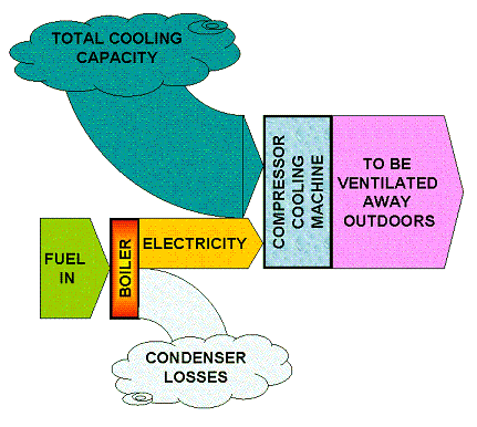
In the most common air conditioning units, electricity is used to produce a cold medium in a compressor cooling machine. The cooling factor for such compressor units is about 2-3, meaning that if you add 1 unit of electricity, the cooling machine will have the capacity to absorb and take away 2-3 units of surplus heat. To make things simple, we now use cooling factors 2 for the compressor machine and 0.5 for the absorption machine.
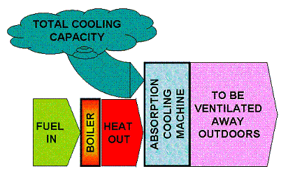
The other option is to use absorption cooling machines instead of compressor cooling machines. Absorption cooling uses only very minor amounts of electricity, but the energy supply to the unit is instead in the form of heat. Absorption cooling is used in propane-fired refrigerators in caravans or for food preservation in remote areas. Since heat regarded from a pure thermodynamical standpoint has a much lower quality than electricity, the absorption coolers need very much more energy and the cooling factor is only about 0.5 or 0.6. Now look at the schematic below, using the cooling factor 0.5 to make things simple. The diagrams show that in case cooling is the only energy service desired, then the combination of condensing power production plus compressor coolers is the one giving the best total system efficiency: 1 unit of fuel energy produces 1 unit of cooling. In contrast, with the absorption cooler, 1 unit of fuel energy produces only 0.5 unit of cooling. None of the schemes has the capacity to produce electricity at the same time. To deliver cooling, both systems require an additional cooling machine on top of the power station itself.
|
|
Now assume that the demand with the customers is for heat instead of cooling.
• With the condensing power station, 1 unit of fuel energy gives (just as assumed above in the schematic) 0.5 units of electricity.
There are now two options:
- The electricity is used in common, simple resistor heaters. Then the total amount of heating produced is 0.5 units.
- The electricity is used in heat pump systems with a heat factor of 2-3 supplied also with geothermal heat or any other low-temperature heat source. Then assuming a heat factor of 2 for simplicity the total amount of heat delivered is 1 energy unit.
• With the CHP station still set at delivering maximum heat 1 unit of fuel energy will produce 1 energy unit of heat.
It must now be clearly stated that these two technologies CHP and condensing production or any other type of electricity production are by no means exclusive. They all have a role to play in any sustainable, future energy supply system. But the two (CHP and condensing) are based on completely different philosophies:
• With CHP, the idea is to use the need for heat as a basis for electricity production.
• With condensing power production, the idea is to produce electricity and nothing else.
Hence, a CHP-plant must always be located reasonably close to the heat sink, be it a greenhouse or a community, a sports centre, a shopping mall, an industrial site or whatever. The size of the CHP-plant is limited by the heat demand. Typically, approximately 40% of the total output from a CHP-plant will be electricity and about 50% heat assuming a total efficiency of 90%. Assuming a heat sink of say 1 GWh/year will then limit the size of the CHP plant to a total of 2 GWh/year and the total amount of electricity in this example can be no more than 0.8 GWh/year.
The fact that the CHP-plants are located close to population centres is also a limiting factor since the fuel transports may become an issue due to noise, light, the need of heavy transports etc. Hence, CHP-plants are rarely much larger than 4-500 MWTH.
The lower size limit for CHP-plants is set by the steam turbine, its efficiency and the total economy. The smaller a steam turbine becomes, the lower becomes its efficiency. At the same time: The smaller the total plant, the relatively more expensive becomes high steam pressures and high steam temperatures. In smaller CHP-plants, currently less than about 10 MWTH, does the electricity conversion efficiency drop to low values, about 20%, and the economy of the plant comes at risk.
Economy of scale
With condensing power production based on fossil fuel there is basically no upper limit to the size of the power station. Fossil fuels are relatively cheap to handle because of their high heating value and if the power plant can be located close to a coal mine, an oil well or a gas pipeline with sufficient capacity and if there is enough cooling medium available then the fuel supply sets the upper limit.
For a CHP-plant the picture becomes slightly more complicated. The economy of the CHP-plant depends on both products heat and electricity being sold on their respective, competitive markets. And there is also a competition between the two products, as will be seen in the following example.
Now introduce the following two technical factors:
ηTOT This is the total efficiency of the plant. Values from the Swedish experience indicate that this value is typically about 0.9, so that in many CHP-plants is 90% of the fuel energy actually converted into marketable products, heat and electricity. Its implicitly assumed that heat is distributed via a large DH-network where the total efficiency is high.
α This is the ratio of electricity to heat in the product mix. Values from the Swedish experience indicate that this value is typically about 0.8, so that the product mix at a total efficiency of 90% consists of about 40% electricity + 50% heat.
These two factors are purely technical and the values should be applicable to most regions.
Further introduce the following economical factors:
fF This is the ratio of total production cost to fuel cost in the plant. Values from a number of Swedish plants indicate that this value is typically about 2, so that in many CHP-plants is half the total production cost directly reflecting the cost for the fuel. This factor is a combination of economy and technology but it would probably be reasonably general.
fEL This is the net income from electricity sale. Assuming the final price paid by a private customer is PEL eurocent/kWh, then this price includes taxes, it includes a cost for the grid and several other implicit fees. The function of fEL is to reduce the private customer price to an income for the plant owner, so that the income from the final sale of 1 kWh of electricity to a private customer generates an income of fEL*PEL to the plant owner. With the Swedish taxes and fees, the value for fEL is approximately 0.25.
fH This is the net income from heat sale. This factor is completely analogous to fEL but for the heat market. Swedish taxes and fees set this at approximately 0.5.
Finally, assume a factor for the relation between the price for heat and the price for electricity with the final, private, consumer fH-EL. The reasons for the private customer to buy district heat are basically two: The superior comfort not to have to worry about the supply of heat for comfort and for tap water and a competitive price. In Sweden, one main competitor to district heat is geothermal heat where a heat pump is used to produce comfort heat and tap water. The heat pump will in this application have a heat factor about 3 so that the final cost for the heat supplied to the house is about 1/3 of the price for electricity disregarding the capital cost. The value for this factor will depend on the local markets and on the local alternatives, but lets assume a value for fH-EL = 1/3, representative for Swedish conditions.
Using these factors, one may now derive an equation for the allowable fuel price to the CHP-plant in relation to the customer price for electricity. The equation becomes:

Inserting values from the Swedish experience as suggested above now yields:

What this means, is that if the final electricity price with a private customer is say 15 eurocent/kWh, then may the fuel price at the plant be no higher than 0.09.15 = 1.375 eurocent per kWh of fuel energy.
So there is a strict upper limit for the fuel price at the plant, as compared to the customer price for electricity, to make a CHP-plant profitable.
In smaller units, what happens is that the total efficiency drops marginally while the value for α will drop significantly.
Since a large fraction of the actual price for biofuel is set by the handling and the logistics, this in turn will again affect the upper size limit for the plant. The biofuel price at the plant will be a strong function of the mean hauling distance and hence the area from where the fuel may be collected becomes limited. In many cases may this be the strictest limiting factor.
SELF TEST
This handbook, except for the four introductory chapters 00-00 through 00-03, is based on a matrix structure and can be studied either by column (= application) or by row (= fuel quality). Depending on how you choose to read it, the tests with the individual chapeters may become slightly different.
TEST what you have learnt along the row about the use of biofuel in different scales!
TEST what you have learnt along the column about different fuels for combined heat-and-power production!
| INTRODUCTORY CHAPTERS 00-00: Global resources 00-01: Current chapter 00-02: Over-all biomass properties 00-03: Fuel/Energy supply | ||||
FUEL↓ APPLICATION→ |
SINGLE-FAMILY HOUSES | LARGER BUILDINGS | DISTRICT HEATING | Download pdf |
|
FIREWOOD Introduction Properties |
Domestic firewood |
NOT APPLICABLE |
NOT APPLICABLE |
NOT APPLICABLE |
|
PELLETS and BRIQUETTES Introduction Pellet properties Briquette properties |
Domestic pellets | Large bldng. pellets | DH pellets |
NOT APPLICABLE |
|
WOOD CHIPS Introduction Properties |
NOT APPLICABLE |
Large bldng. chips | Chips for DH | Chips for CHP |