02-03: Wood chips for heating in larger buildings
The main limitation
As has been pointed out previously, the section about combustion in chapter 00-01, there is a connection between the attainable quality in the combustion process and the fuel uniformity. There is also a connection between the uniformity of the fuel, the fuel particle size, and the physical size of the combustion equipment. These interconnections finally boil down to a general statement: To answer up to high demands on environmental performance, small combustion units must be supplied with uniform fuels, preferably fuels having particle sizes significantly smaller that the cross-sectional measures of the combustion equipment.
From a thermal point of view will "larger buildings" include most anything from smaller office buildings with a heating demand of maybe 30-50 kW and all the way up to large shopping malls or greenhouses where the thermal power demand may rise well above 1000 kW during cold days. The lower end of the segment is touching the domestic scale and pellets are the recommended fuel but in the high end wood chips become an attractive alternative.
The main technology
The fuel is pushed onto a perforated grid, a grate, through which air is supplied from underneath. This is called grate-firing and is a technology employed from thermal powers about 50 kW and all the way up to 20-30, in coal applications well above 50 MW. While the particle is burning it is successively moved from the feeding end of the grate to the discharge end where ashes are removed.
Three major designs:
Looking aside from the travelling grate with spreader-stoker, commonly used in large-scale applications, there are three major designs employed in the smaller scales:
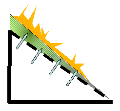
The simplest way to employ grate-firing is to use a fixed grate. Fixed grates are preferably used in small scales where the investments cost is crucial and where mechanical simplicity is important.
In this case, the perforated grate is inclined; fuel is fed to the upper end and slides successively down the grate under the influence of gravitation.

In theory, a fuel particle cannot pass across the low end of the grate until the particle below it has burnt out completely and more-or-less disappeared. In practice, this is not so clean but fuel particles tend to topple and tumble so that total fraction of unburned particles found in the ash may be significant. This becomes very pronounced in case a fixed grate designed for rough-surfaced, low-density and irregularly-shaped wood chips is instead fed with smooth-surface, high-density and cylindrical pellets. The pellets will quite happily tumble and topple down the slope and a severe drop in burnout efficiency would be anticipated as the result from such a fuel change.
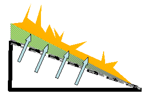
Next simplest is the vibrating grate. In this case, the grate is vibrating, thus improving and simplifying the movement of the particles down the grate.

This introduces mechanical devices for the vibration, increases the investment cost and makes the whole construction more complicated. Since the vibration contributes to move the particles, the inclination of the grid needs not be as steep as with a fixed grate.
The problem with toppling and tumbling is then reduced and hence will a vibrating grate generally be more flexible with respect to fuel. On the other hand does the vibration tend to increase the amount of fly ash elutriated from the fuel bed.
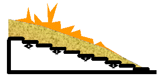
The most complicated but most flexible is the moving grate, the preferred technology in many scales or if fuel flexibility is paramount.

The moving grate resembles a flight of stairs but each step slides back and forth with an adjustable period. Because of the sliding motion, the fuel is successively pushed down the stair. The "steps" are perforated so that air can penetrate from below though this is omitted in the schematic. With some designs, the fuel movement may be completely horizontal though the most common is to have an inclination. The geometry of the steps length and height in combination with the amplitude and period of the sliding motion, will mainly determine the amount of tumbling in the fuel bed as well as the fuel particle residence time while the almost horizontal arrangement of the bed as such will minimize toppling. Hence will a moving grate be the most flexible with respect to fuel. On the other hand will the complicated mechanics make it the most expensive of the three.
Ashes and ash melting
With all three designs for the grate, the theory is that the ashes shall fall of from the grate down into a trough in the bottom of which a screw brings it out from the combustion chamber.
Wood chips may exhibit most ash melting temperatures in a very wide temperature range and ash melting is a considerable problem in combustion units operating on chips. Comparing the chemical composition of biofuel ashes to other substances you may (or may not) realize that it to a great extent resembles glass. Hence, when the ashes melt, they will form a very sticky and viscous melt which becomes extremely hard once it solidifies.
On a fixed or a vibrating grate, such a solid cake of thick glass will block the holes for the air supply and may also slide down to effectively cover and block the trough so as to prevent the ash from falling down and be transported out of the combustion chamber.
With a moving grate, where the "steps" in the "flight of stairs" are moved back and forth by aid of hydraulics, may the sheet of glass instead be broken up into pieces and hence removed.
Fuel flexibility
The low angle of inclination in combination with the forced movement of the grate elements in the moving grate combine to make this the most fuel flexible combustion technology in the scales applicable for larger buildings.
The limit with respect to fuel flexibility is mainly set by the elutriation of small fuel particles from the grate by the vertical gas flow. In case of briquettes, for example, the briquettes will usually break during the feeding process and a large amount of the fuel actually fed will be cutter shavings. The cutter shavings will readily be elutriated from the fuel bed and will be combusted in the freeboard above the fuel bed. This will have an adverse effect on the total efficiency as well as on the environmental performance.
The second limitation is set by the combustion chamber walls. In a combustion chamber dimensioned for wet fuels, like wet wood chips, will the walls be insulated to maintain a sufficiently high combustion temperature. In a combustion chamber aimed for dry fuels, on the contrary, will the walls be water cooled to avoid too high combustion temperatures. With a dry fuel fired in a combustion chamber with insulated walls will the temperature become extremely high with ash melting, nitrogen oxide formation and high thermal stress for the wall ceramics as consequences. In the opposite case - a wet fuel fired in a combustion chamber with cold walls - will the combustion not go to completion with emissions of hydrocarbons as a consequence. This limit to the fuel flexibility then has nothing to do with the grate itself.
Conclusions with respect to fuel flexibility
The consequences of the above are:
• The fixed grate is the cheapest, i.e. with the lowest capital cost but is limited with respect to fuel flexibility because it is sensitive to the physical properties of the fuel as well as to ash melting. Hence will the low capital cost be counteracted by the fact that the possibility to choose the cheapest fuel is limited in the long run.
• The moving grate is the most expensive, i.e. it is the technology with the highest capital cost. On the other hand will the fuel flexibility facilitate use of cheap fuels and the high capital cost may thus be compensated by a low variable cost, i.e. fuel cost, in the long run.
Considerations concerning storage
Wood chips may exhibit most any moisture content ranging from 10-15% in the case of saw-mill residues and all the way up to 55% in the case of felling residues. This affects both the heating value and the density and to further complicate the picture, the degree of close packing with irregular particles like chips is also vary much variable. Generally speaking, though, is the energy intensity in chips storage very low typically less than 1.5 MWh/m3 bulk volume sometimes as low as 0.5.
Wood chips are also a biologically active material and the establishment of mould and in the worst case rot fungi may provide a local problem not only for the working environment but also in the close vicinity of the storage.
SELF TEST
This handbook, except for the four introductory chapters 00-00 through 00-03, is based on a matrix structure and can be studied either by column (= application) or by row (= fuel quality). Depending on how you choose to read it, the tests with the individual chapeters may become slightly different.
TEST what you have learnt along the row about using wood chips in different scales!
TEST what you have learnt along the column about different fuels in larger buildings!
| INTRODUCTORY CHAPTERS 00-00: Global resources 00-01: Energy fundamentals 00-02: Over-all biomass properties 00-03: Fuel/Energy supply | ||||
FUEL↓ APPLICATION→ |
SINGLE-FAMILY HOUSES | LARGER BUILDINGS | DISTRICT HEATING | COMBINED HEAT-and-POWER |
|
FIREWOOD Introduction Properties |
Domestic firewood |
NOT APPLICABLE |
NOT APPLICABLE |
NOT APPLICABLE |
|
PELLETS and BRIQUETTES Introduction Pellet properties Briquette properties |
Domestic pellets | Large bldng. pellets | DH pellets |
NOT APPLICABLE |
|
WOOD CHIPS Introduction Properties |
NOT APPLICABLE |
Download pdf | Chips for DH | Chips for CHP |