00-03: Basic considerations concerning fuel and energy supply...
The two main concepts
Supplying end users with their energy services can be done in two major ways:
• A proper fuel may be distributed among the end users and each house or household makes use of the fuel to produce their own energy.
• The fuel is supplied to a central energy production plant where a suitable energy carrier is supplied and the energy is then transported to the individual households.
The first principle fuel distribution in combination with a decentralised energy conversion has been used traditionally with firewood, later coal, coke, kerosene, propane and oil, today fossil gas distribution to households where the fuel is burnt to provide light, cooking heat, hot tap water and comfort heating.
The second principle centralised energy production with subsequent distribution of the energy carrier is what is used with modern electricity grids as well as in district heating and -cooling networks.
The advantage with the first principle decentralised production is that it is reasonably robust because there are typically many actors involved and there will be a multitude of equipment at the user end, making up for a certain redundancy in the system. Hence; If the supply of pet-coke would fail and a number of households suffered from that, there might still be coal or firewood available that could in emergency be used in the pet-coke stoves.
The drawback with the first principle can best be illustrated by the situation in London during the early decades of the 1900's when individual heating of houses was prevalent, based on coal-firing. This was the background and the cause of the infamous London Smog causing acute as well as creeping deaths by lung diseases and leading up to a prohibition to coal firing.
So obviously the major advantage with the second concept, centralised production, is the possibility to install advanced flue gas cleaning and take measures to minimize environmental impact from the energy production plants. Also, a larger plant may use more advanced technology because it can carry the cost for advanced process control and it can carry the cost associated with a certain degree of fuel flexibility. The large scale plants surrounding for example a city should also be planned and designed bearing redundancy in mind, so that not all production units rely upon the same fuel but that a certain amount of flexibility is built into the system, if not into the individual plant.
The drawback is then that the distribution system may be susceptible to disturbances, sabotage or even terror attacks. A certain redundancy is always desirable but a distribution network will contain bottlenecks where a malfunction may cause severe effects. This holds true for fossil gas pipelines, for electricity grids and for district heating or cooling networks alike and cannot be avoided.
Supplying district heating and cooling
District heating is supplied by hot water forward temperatures ranging from 65 to 110 °C depending on season. The water is heated in boilers or it may be heated by the exhaust steam from steam turbines in the case of combined heat and power production plants. In some places around the world has steam been used for district heating but such systems become more complex and hence more expensive and they also become more dangerous than hot water systems and the steam systems are successively phased out.
The hot water is distributed to the end-users by pipes in the ground and the heat is extracted from the water by aid of heat exchangers in each building. The heat exchanger will contain two loops one for the hot water to the radiators in the building and another one for the hot tap water. Hence the district heating network will in itself contain one or two circuits:
• In case of hot-water boilers will the boiler water in the primary circuit transfer its heat to the district heating circuit via a heat exchanger in the boiler house and then the district heating circuit will again exchange heat with the individual houses, the customer circuit.
• In case of CHP will the primary circuit be a steam-raising circuit and the district heating circuit will exchange heat with the primary circuit at the turbine exhaust.
The tubes in the district heating circuit will be dimensioned so that the hot water travels through the pipes with a velocity of approximately 3-6 m/s. A higher velocity for the water will certainly reduce its residence time in the pipes and will thus reduce the temperature losses but on the other hand will a higher velocity increase the power demands for the main pumps roughly in proportion to the velocity squared. So doubling the water velocity from 3 to 6 m/s in a given network will approximately quadruple the power consumption in the pumps. On the other hand will too low a velocity lead to too large temperature drops in the system.
To control the power distributed through the district heating system, the forward temperature is controlled and set to high temperatures (up to 120 °C) during winter while during summer they are typically low maybe only 65-70 °C.
Monitoring and metering for billing is done in the heat exchangers in the individual buildings where the flow of district heating water through the heat exchanger is logged together with the district heating water temperatures before and after the heat exchanger. Hence the customer is billed for the energy extracted from the network and dripping tabs or leaking joints will be fully paid by the end user and will not hit the energy supply company.
District cooling is arranged in full analogy with district heating only the medium is not hot but cold water. Typical forward temperatures in district cooling are 4-10 °C. For cooling, the installations inside the individual buildings need be more complicated than for heating: To cool down a building it is not sufficient to have cold, vertical surfaces underneath the windows as is the case for heating but the indoor air itself must be cooled down. Hence centralised cooling in single buildings is best installed from the beginning and it may be complicated to install central cooling in already existing buildings.
Solid fuel supply
We shall first consider some general aspects that are important to bear in mind when planning a fuel distribution and supply system.
The quality will change through the supply chain - moisture

|
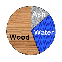
When fresh harvested, biomass may contain up to
or even more than 65% water, by weight. To get the picture, visualize 45 sheets of normal printer paper drenched in 0.65 litre of water. |
| You will realize that this mixture is not very desirable as a fuel
but will need to be dried to become useful. |
A European federal standard EN 14588:2003 defines the terminology to be used within the area and to summarize one may say that at high moisture contents, the biomass is really just biomass while already a simple drying process will be sufficient to change its status from biomass to biofuel.

The moisture content in growing plants depends on the season so that during the most intensive growth period the water content is at its highest (maybe 65%) while during winter, when the plants more or less hibernates, the water content is at its lowest (maybe 45%).
Only very scarcely can the harvesting period be determined with respect to water content, but typically the moisture content is what-it-is when biomass for energy is harvested, and the supply chain must be designed to cope with this. The best thing is if the supply chain itself supports the transformation of biomass into biofuel of a proper quality for the subsequent use.
Forced drying is a very expensive process so to maintain a reasonably low cost throughout fuel handling, one wants the drying process to take place by natural means and not to use forced drying. However, natural drying by sun and wind is a slow process, so to rely upon open-air drying of the fuel, allowance must be made for sufficient time during the fuel supply and there will be quite some volumes of fuel in store for drying at any one time. This implies a capital cost to the system, a cost that should be accounted for in any economic evaluation.
Firewood supply
The supply of firewood should be organised so that after cutting and splitting, the chunks are given ample time for drying exposed to wind but protected from rain. At delivery, the firewood should have moisture content no more than 30% by weight, preferably less.
The bulk density of firewood when transported in a container or on a truck is approximately 300 kg/m3 while the bulk density with wood logs is about 400 kg/m3. Hence, it is advantageous to perform cutting, splitting and drying as close to the end user as possible.
Wood chip supply
The efficient handling of felling residues starts already during the felling operation.
At the time of felling, a certain reinforcement of the soil at the site is typically needed to prevent too severe damage by the heavy machinery but the assortment aimed for fuel should be separated already during the cutting and de-branching operations and put to the side of the driveways.
In direct connection to the felling operations, a forwarder with a grapple should be instructed to build windrows in appropriate places close to the strip road. The windrows are then covered with waxed paper and left for 6-12 months for open-air-drying.
When needed, the material is chipped from the windrow to a container and transported to the energy plant.
The characteristics of the described supply chain are the following:
• Drying takes place in un-comminuted material placed in a porous structure preventing microbiological attacks by mould and rot fungi. This preserves the material while at the same time the porous structure allows wind access and promotes drying.
• During drying in the windrows, the green parts of the material will fall off to a great extent and will thus remain at the felling site. This reduces the extraction of nutrients from the site.
• The bulk density of branches and tops during transport is typically only about 150 kg/m3 and hence this material should not be transported any long distances. Chipping into containers at the felling site increases the bulk density for transport to about 400 kg/m3 and hence radically improves transport economy.
• Since, basically, the wood chips should be produced "on demand", this system calls for trucks to be available to transport the fuel from the forest to the energy plant.
A recently developed alternative to this supply chain is to bale the fuel assortment in direct connection to the felling operation. With the modern baling machines, the bales would typically be about 3 m long, have a density about 400 kg/m3 and be simple to handle using standard wood-log handling cranes and equipment. Tests performed indicate that drying of such bales occurs in a similar way to drying in windrows while handling becomes cheaper since the bales can be transported to the energy plant and hence the chipper needs not be mobile. Since the bales are reasonably compact, they can be stored close to or on site at the energy plant. Using this system, the long-distance transports from forest to plant can be co-ordinated with the felling activities and disconnected from the energy demand.
The drawbacks are that the green parts are completely removed from the felling site so that the need for ash recirculation becomes more pronounced and that the green parts are introduced to the combustion unit introducing more ash with different quality to that of the material dried in windrows.
The third main alternative is to establish a central wood chips storage terminal and to store comminuted material for a long time. Several microorganisms will thrive given cellulose to eat, water and shelter so that a comfortable temperature can be maintained. This is exactly what is offered inside a pile of wood chips and field tests have shown that the establishment of microorganism populations inside wood chip piles occurs already within the first 24 hours after the pile is dumped. Also, a wood chip pile is not penetrable to wind, so the drying will be highly inefficient.
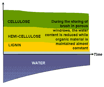
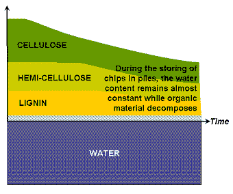
The general difference between the two extreme cases storing in windrows in combination with delayed chipping and direct chipping followed by storing in chip piles is qualitatively illustrated in the diagram below.
 |  |
The diagrams indicate how the total amounts of cellulose, hemi-cellulose and lignin may remain (almost) constant during storage in windrows even for a storage period extending over 24 months. The moisture content though will decrease rapidly in the beginning and finally approach equlibrium. Obviously, the moisture content behaviour depends strongly on the initial moisture content as well as on the actual season drying is more rapid during summer than during winter but the diagram illustrates the general trend that drying is most efficient during the first few months and slows down after the initial period.
The reduction i.e. the microbiological consumption of cellulose, hemi cellulose and lignin during storage in wood chip piles is qualitatively illustrated in the left-hand side diagram. During a period of 24 months the total losses of combustible material may well exceed 30% of the initial material and already in 12 months may 20% of the combustible material be lost. As a rule of thumb, deterioration may be 1-5% per month, 2-3% as a typical value. At the same time, it must be understood that the material in the pile dries only very marginally. Finally, the microbiological activity inside the pile also releases heat that may, in the worst case, lead to an auto-ignition of the pile. The risk is the highest when the chips pile contains mixtures of different qualities like bark chips mixed with stem wood chips.
The advantages with a central terminal storing wood chips are that the transports of chips to the energy plant can be shortened and that the chipper needs be engaged only for short campaigns, whether chipping takes place in the forest or at the terminal.
Within the energy plant, wood chips are best transported on conveyor belts. The repose angle for wood chips is such that a flat conveyor belt may be inclined up to 30° to horizontal. For steeper transports, screw conveying is preferred.
Wood pellet supply
Wood pellets are best produced from dry saw dust in carpentries, sometimes complemented by dry cutter shavings from planning. To produce good and durable pellets, the material must not have higher moisture content than about 12-15% and it needs be milled to sizes below 1 mm. Starting from carpentry-dry sawdust and shavings minimizes the drying cost.
Wood pellets are too dry and too compact to provide good living conditions for micro-organisms. This does not mean that the storing and handling of wood pellets is free from problems but it is much less troublesome than the handling of chips.
There are mainly two different ways to handle and distribute wood pellets, in bulk or in bags.
In case of bulk distribution the pellets are blown into the end-user storage hopper by compressed air and the mechanical durability of the pellets is one of the most crucial factors for the total system performance. The central store for the pellets may be in a silo or if the storage time is not too long only underneath a rain-protective roof without side walls. High-quality pellets are compact enough to withstand outdoor climate for a few weeks as long as they do not become wet, so a fairly simple rain protection can be sufficient for short term storage. In case pellets are stored in bulk in a closed compartment like a silo, or when they have just arrived onboard a ship, one must be aware that pellets are not completely inert but that they do oxidize also at ambient conditions. Thus, in the closed compartment, carbon monoxide may be present and the oxygen content in the enclosure atmosphere may be low. Before entering a closed pellet bulk storage room one of two precautions should be taken:
• Ventilate the room well to guarantee that the atmosphere is fresh air
• Put on a closed breathing mask with an air bottle
In case of bags mainly used in systems where single households are the end-users the risks with auto ignition and oxygen depletion/carbon monoxide formation are eliminated. If outdoor storage is an option, the bags must be water tight, since otherwise the pellets will degenerate to wet saw dust inside the bags and form solid chunks. Thus, reloading and unloading the bags requires some precaution so that the bags are not damaged.
Pellets can typically not be transported on conveyor belts in case there is an inclination, but screw conveying or pneumatic transport is generally the best.
Wood briquette supply
Like pellets, briquettes are mainly manufactured at carpentries and planning mills but the briquetting press is cheaper than the pellet press, so sometimes briquetting is preferred to pelletizing.
While pellets are durable enough to maintain their shape all the way into the combustion chamber (unless they are of inferior quality), briquettes are typically too brittle and tend to disintegrate in the feeding system. Unless care and precaution is taken throughout the supply system, the briquettes may already disintegrate during loading, unloading and transport. Hence, briquettes are mainly to be regarded as a transport packaging to increase the bulk density while the actual combustion in plants fed with briquettes typically occurs with saw dust and with cutter shavings.
Briquettes are even more sensitive to water than pellets and are best stored and handled indoors though the may be stored under roof without walls for shorter periods.
Wood briquettes find their main use in smaller automatic units while small amounts are also marketed and sold for household use.
Wood powder supply
Again from carpentries, dry grinding dust may be available. The ash content in grinding dust will typically be high since the wear from the grinding paper will be mixed with the dust, but it will exhibit very small particle sizes making it a good fuel for pulverized fuel combustion without additional grinding or milling.
Wood powder for fuel is also produced industrially, in that case preferably from saw dust or shavings that are further milled in hammer mills.
Wood powder is delivered in trucks similar to petrol trucks and is loaded and unloaded using pneumatic transport with a protective gas in closed systems. Wood powder is highly explosive and not only must it be stored in oxygen-free atmosphere but also must sparks from friction or from static electricity be avoided by a proper system design.
The safety demands on the supply and handling systems render high capital costs for wood powder firing systems but then the operational cost may be kept low since there are less moving parts in pulverized fuel burners than in grate-fired boilers and since the pressure demands are lower than in fluidized bed systems. Hence pulverized fuel finds its application mainly in large plants.
TEST what you have learnt!
This was the last one of the over-all introductory chapters. You are now advised to try taking the TEST covering all four introductory chapters. This test consists of 10 questions chosen at random from the previous tests and every time you start this test there may be new questions... A bit tougher, then.
| INTRODUCTORY CHAPTERS 00-00: Global resources 00-01: Energy fundamentals 00-02: Over-all biomass properties 00-03: Download pdf | ||||
FUEL↓ APPLICATION→ |
SINGLE-FAMILY HOUSES | LARGER BUILDINGS | DISTRICT HEATING | COMBINED HEAT-and-POWER |
|
FIREWOOD Introduction Properties |
Domestic firewood |
NOT APPLICABLE |
NOT APPLICABLE |
NOT APPLICABLE |
|
PELLETS and BRIQUETTES Introduction Pellet properties Briquette properties |
Domestic pellets | Large bldng. pellets | DH pellets |
NOT APPLICABLE |
|
WOOD CHIPS Introduction Properties |
NOT APPLICABLE |
Large bldng. chips | Chips for DH | Chips for CHP |